

To check the trim of a paraglider, the lines must be pre-tensioned with a defined force. To achieve this, you need a tensioning device. This article explains how I set it up.
There are ready-made tensioning fixtures such as the one from Parafly24 including a laser measuring device and app or, alternatively, do-it-yourself versions, some of which are listed on the we-measure.io website. However, none of the do-it-yourself versions appealed to me, so I made my way to the DIY store and collected the material I needed for the tensioning device. Due to my limited manual skills and the few tools I have at my disposal, I came up with the simplest possible construction. I bought the following materials from the DIY store or ordered them online:
- Aluminium round bar 5 mm
- Aluminium rectangle 40×40 mm
- Aluminium flat bar 2×40 mm
- Aluminium flat bar 2×20 mm
- Ball bearing slide with 27 mm groove
- Idler pulley
- 4 mm screws with stop nuts
- Self-adhesive Velcro strips, double-sided adhesive tape
- Lead weights 5 kg and bag
- Nylon rope
- Carabiner
Costs of around €40.00 are to be expected (excluding the lead weights that I already use for the rescue pack).
Tools required for assembly:
- Drilling machine
- Metal drill bits, various sizes
- Screwdriver
- Sheet metal peel drill
- Vice
- Hammer
- Hacksaw
- Ratchet box
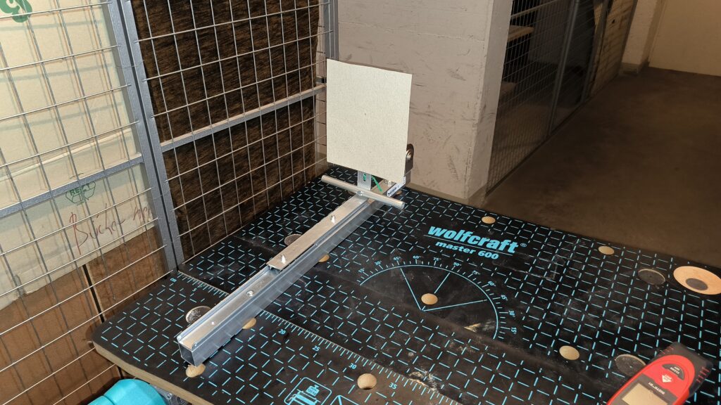
I attached the ball bearing slide to the aluminium rectangle with 2 screws. Make sure to use screws with flat heads (included with the ball bearing slide) so that the movable rail can move over the screws. It is advisable to use stop nuts so that they do not come loose by themselves.
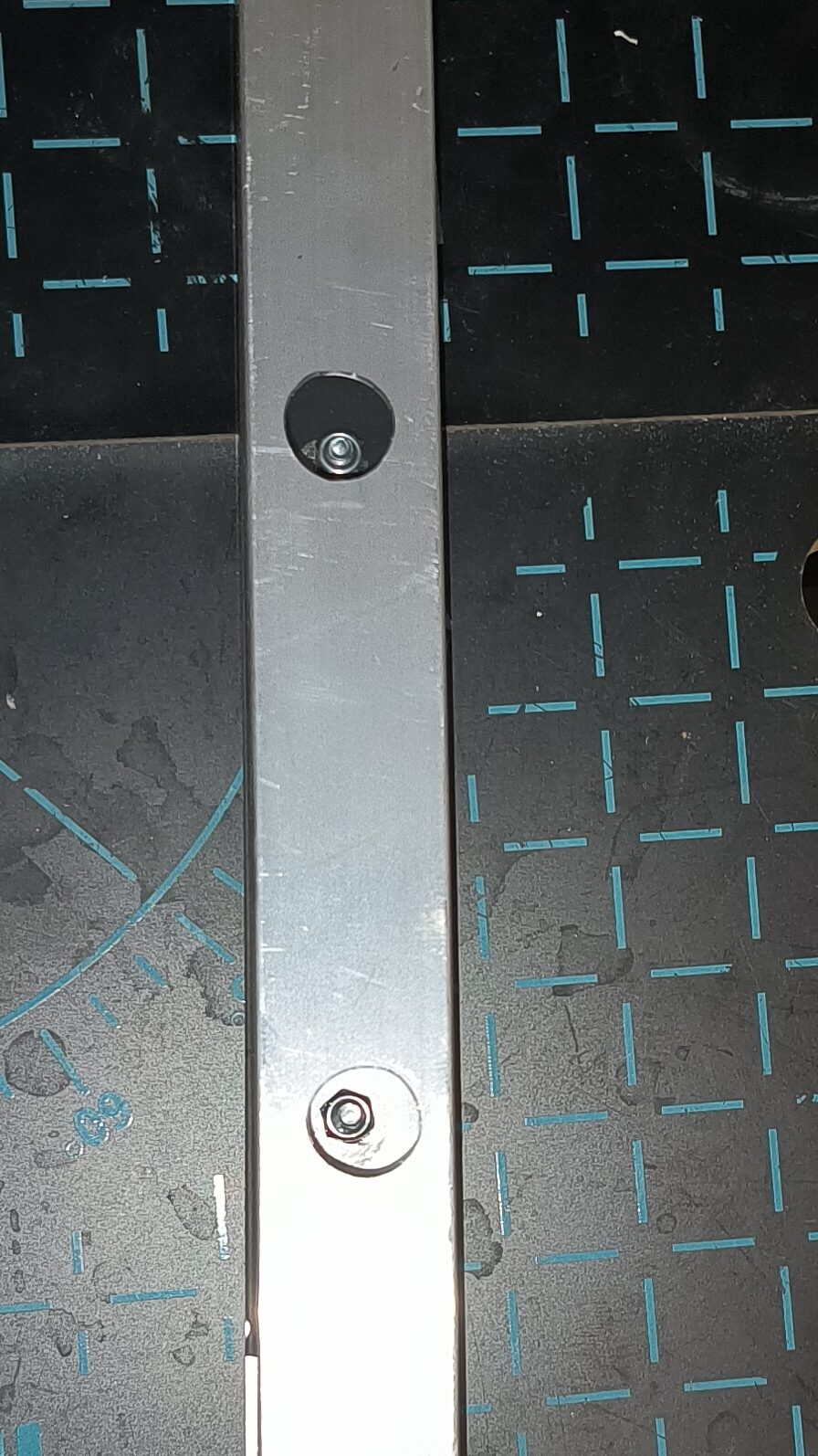
I enlarged the holes on the back with the sheet metal peel drill to fit the ratchet box nut for tightening the lock nuts. A bit of fiddly work to get the nuts onto the screws, but doable.
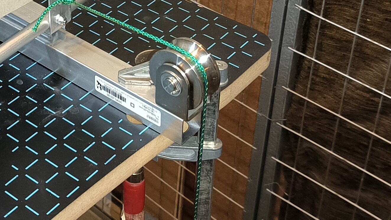
In the rear part of the aluminium rectangle, the deflection pulley is mounted on the aluminium rectangle in the same way.
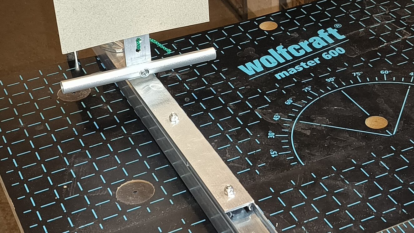
I bent a 90° angle with the 40 mm aluminium flat bar. This holds the aluminium round rod, for later attachment of the risers, and the target (cardboard), for later aiming with a laser measuring device. The target disc is attached with double-sided adhesive tape. Two holes should also be provided for the rope to pass through for tensioning.
As the risers and the target are mounted at the same height in my design, there is no offset. This is an advantage over other designs where the risers and target are often mounted at different heights. This offset must be taken into account later when measuring.
The whole thing is mounted on the carriage of the ball bearing slide. Screws with flat heads should also be used here. The slide should run free of obstacles.
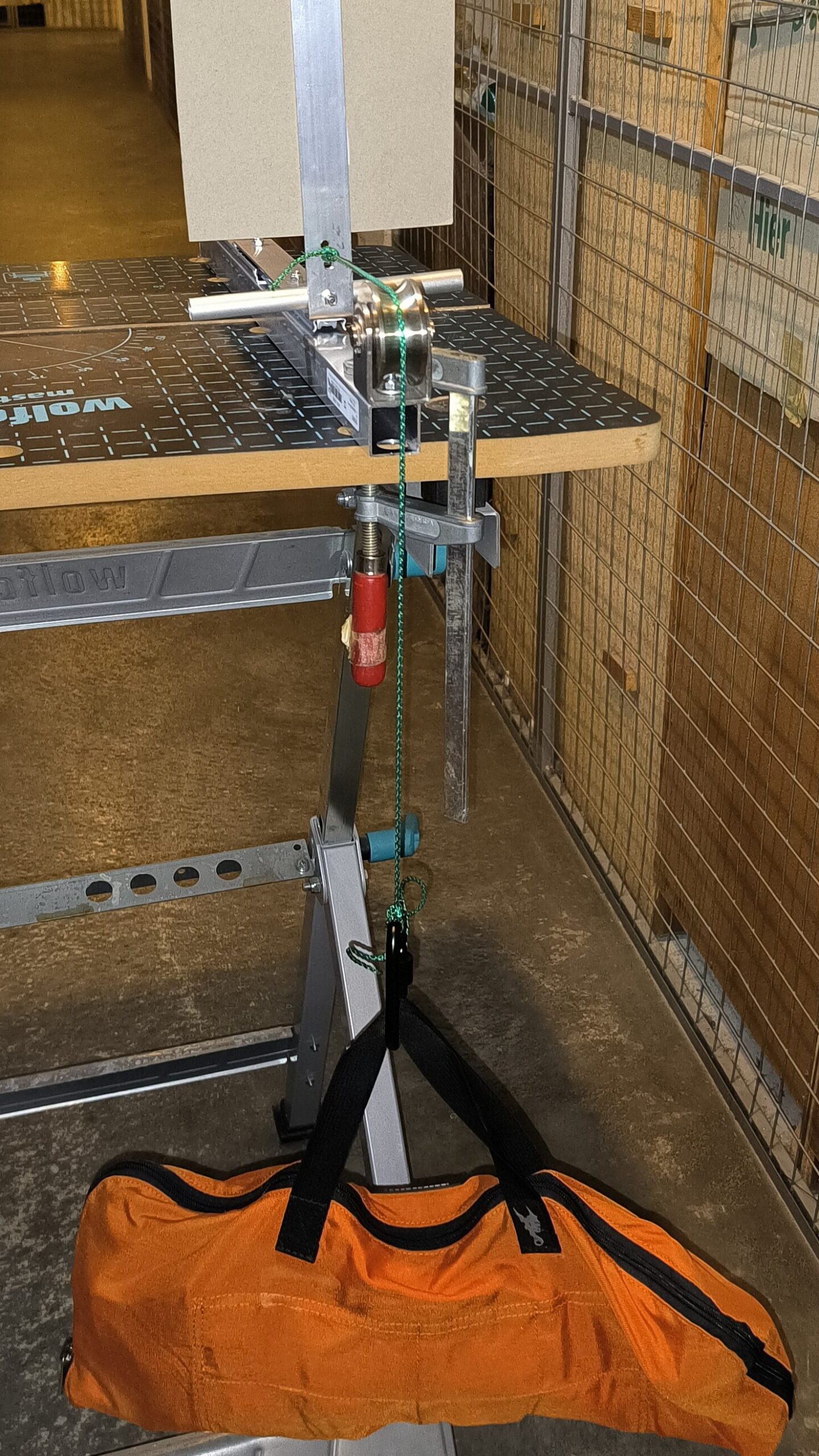
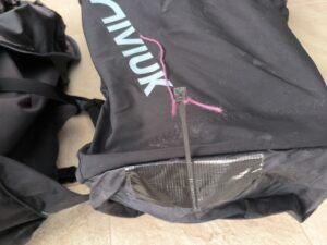
The nylon rope is used to connect the sled to a carabiner via the pulley. The bag contains the 5 kg lead weights. The tensioning device should be fixed to the table with a screw clamp.
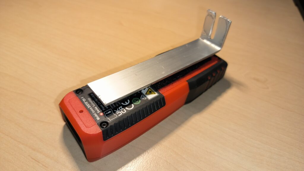
Last but not least, I bent a bracket from the 20 mm aluminium flat bar. A slot is sawn into this to accommodate the lines later. The slot must be well deburred so that the lines are not damaged. The bracket is attached to the laser measuring device with Velcro tape.
I explain how I check the trim of the paraglider using we-measure in a separate article.

Pingback: Paraglider trim check with we-measure - Ad Nubes | Paragliding blog
Pingback: Paraglider check at the Checkerei - Ad Nubes | Paragliding Blog